Table of Contents
Introduction
Digital signal processing has two components: signals and filters.
A signal is a time-series which has information (RF vocabulary) and filters are useful in applying a desired affect to a signal. These affects can be:
- enhancing information elements of a signal,
- attenuating or minimizing noise,
- or some other modification.
The following sections will highlight how an FIR filter can be used to minimize noise in a receive signal which enhances the information content. Trade-offs will be discussed between how much noise can be minimized with how much distortion can be applied to the underlying signal.
More posts on FIR filtering:
Time Invariant Filters
The introductory type of filter encountered in the undergraduate education is the time-invariant (TI) filter. A TI filter is one whose impulse-response does not change with time. Applying the filter against the same signal a nanosecond from now or 15 years from now will produce the same response. A signal x[n] is related to the filter output y[n] through discrete-time convolution,
(1) ![]()
or equivalently,
(2) ![Rendered by QuickLaTeX.com \begin{equation*}y[n] = \sum_{k=-\infty}^{\infty} x[k]h[n-k],\end{equation*}](https://www.wavewalkerdsp.com/wp-content/ql-cache/quicklatex.com-47c804649b70b2d0d5e8d162462f8320_l3.png)
Delaying a signal x[n] by k samples, x[n-k], and passing it through a time-invariant filter h[n] results in the same delay of the output with no other modifications,
(3) ![]()
Moving Average FIR Filters
There are two types of TI filters; infinite impulse response (IIR) filters which have feedback and finite impulse response (FIR) filters which do not have feedback. A moving average (MA) filter is an example of an FIR filter. Consider a length-3 moving average filter
(4) ![]()
where x[n] is the input signal and y[n] is the output of the MA filter. Each output is the average of the three last inputs. For example,
(5) ![]()
(6) ![]()
(7) ![]()
Visually the filter can be represented by the blog diagram in Figure 1.
![Figure 1: A moving average filter is implemented by delaying the input signal x[n] and then scaling by 1/3 and summing all results.](https://www.wavewalkerdsp.com/wp-content/uploads/2021/09/movingAverageLength3-768x488.png)
Each of the filter weights are 1/3 and the MA filter can be represented by
(8) ![Rendered by QuickLaTeX.com \begin{equation*}h[n] = \begin{cases}1, & n = 0, 1, 2 \\0, & \text{otherwise}.\end{cases}\end{equation*}](https://www.wavewalkerdsp.com/wp-content/ql-cache/quicklatex.com-ac695a1dfa35fca9e959a4d78bcd57e1_l3.png)
A moving average filter will reduce noise fluctuations in a receive signal. Figure 2 is an example of a pulse train signal. Noise is added to the pulse train and then the length-3 MA filter is applied to reduce the variations in the signal due to noise.
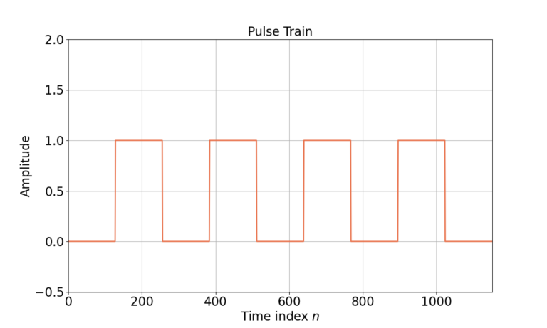
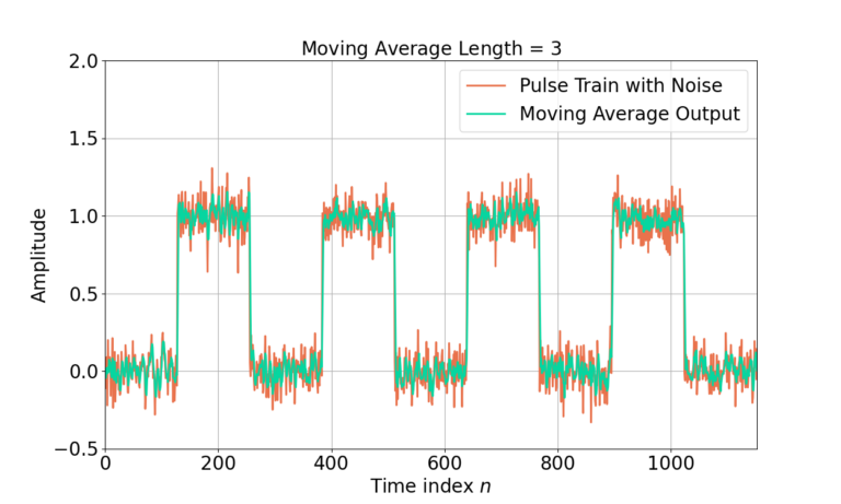
The impact of the MA filter can be seen in the time domain. How does it work in the frequency domain?
Moving Average Filter in Frequency Domain
The Z-transform Z{} can be used to translate the difference equation h[n] into the frequency domain H(z),
(9) ![]()
(10) ![]()
(11) ![]()
Substituting (10) and (11) into (9),
(12) ![]()
Gathering like terms in X(z)
(13) ![]()
allows the transfer function H(z) to be written as
(14) ![]()
Substituting
![]()
into (14),
(15) ![]()
The magnitude-squared response ![]() can by found by
can by found by
(16) ![]()
where * is the conjugation operator. Substituting (15) into (16),
(17) 
Substituting (reference)
![]()
into (17),
(18) ![]()
and converting into dB,
(19) ![]()
Figure 4 gives the magnitude-squared response of the filter H(z) in dB
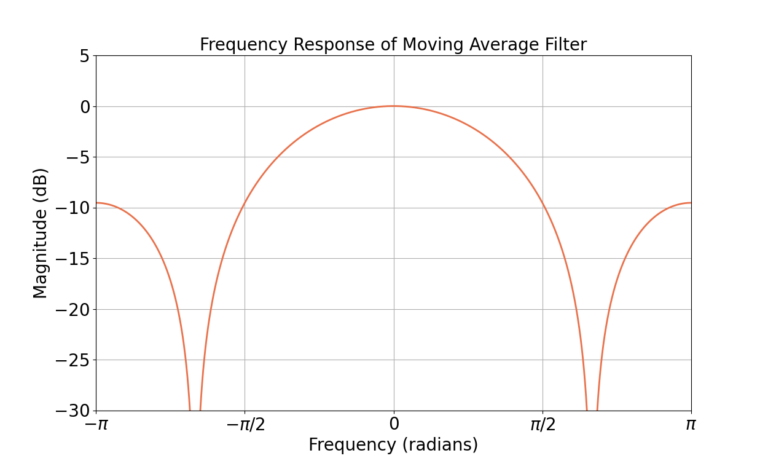
The low-pass nature of the MA filter reduces the impact of high frequency noise, which is the affect seen in Figure 3. The following section will analyze how the MA filter effects the signal and noise in the frequency domain.
Analyzing Filter Impact in Frequency Domain
The input signal x[n] contains both signal s[n] and noise w[n],
(20) ![]()
The filter h[n] low-pass filters both s[n] and w[n],
(21) ![]()
or equivalently in the frequency domain,
(22) ![]()
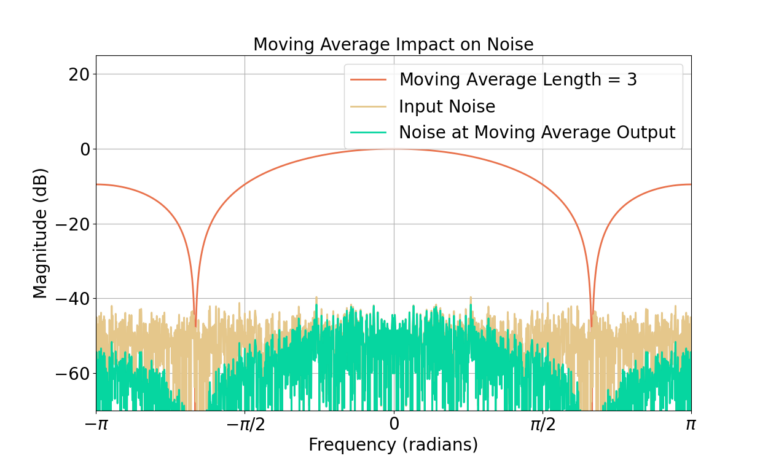
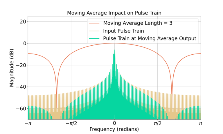
Figure 5 shows how the MA filter reduces the noise at high frequencies in the frequency domain. Similarly Figure 6 shows the frequency response of the pulse train signal is much less effected by the MA filter.
Increasing Filter Length
The previous section showed that a length-3 MA filter reduces the impact of noise by filtering out the high frequency content with little impact to the pulse train signal. If 3 filter weights are good, more are better … right? What will happen if we increase to length 63? Will there be any unintended consequences? (Yes.)
Figure 7 gives the output of a length-63 MA filter in the time domain with the same input pulse train signal.
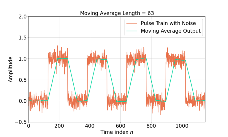
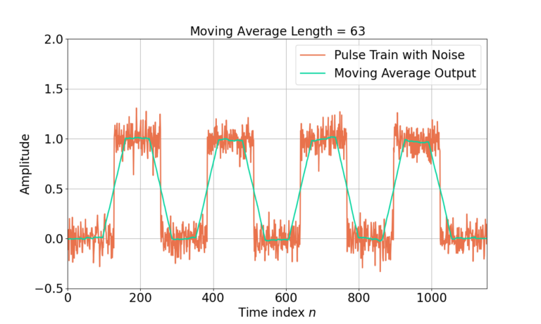
Increasing the filter length from 3 to 63 has created noticeable distortion of the underlying pulse train signal. A period of ramp up and ramp down between pulses can now be seen in the filtered signal as well as a time-shift. Where did this come from? Let’s look to the time domain first.
Analyzing Moving Average in Time Domain
An input signal x[n] is defined to have a single cycle of a pulse,
(23) ![Rendered by QuickLaTeX.com \begin{equation*}x[n] =\begin{cases}1 & 1 \le n \le 7 \\0 & \text{otherwise}. \\\end{cases}\end{equation*}](https://www.wavewalkerdsp.com/wp-content/ql-cache/quicklatex.com-601c2a23547949976299137d097ebd0b_l3.png)
Figure 8 demonstrates the starting values for all elements in the block diagram.
![Figure 8: The starting state of the MA filter when x[n] = 0 for n](https://www.wavewalkerdsp.com/wp-content/uploads/2021/09/movingAverageLength3_input000-768x488.png)
The first 1 is passed into the filter for x[1] = 1 and Figure 9 shows the state of the filter. Figures 10 and 11 also show the response for x[2] = 1 and x[3] = 1.
![Figure 9: The state of the filter at n=1 when x[1] = 1.](https://www.wavewalkerdsp.com/wp-content/uploads/2021/09/movingAverageLength3_input001.png)
![Figure 10: The state of the filter at n=2 when x[2] = 1.](https://www.wavewalkerdsp.com/wp-content/uploads/2021/09/movingAverageLength3_input011-768x488.png)
![Figure 10: The state of the filter at n=1 when x[1] = 1.](https://www.wavewalkerdsp.com/wp-content/uploads/2021/09/movingAverageLength3_input111-768x488.png)
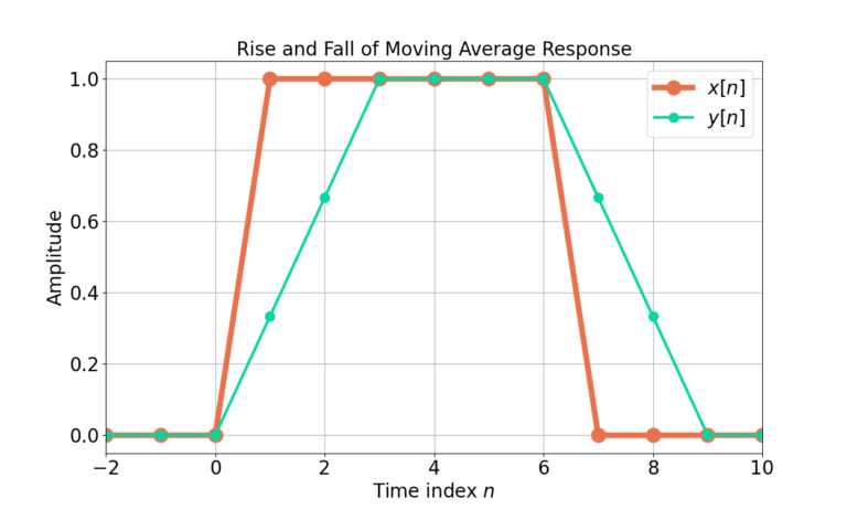
Figure 12 gives the output y[n] for all x[n].
Correcting for Filter Delay
The input signal x[n] is 6 samples of 1’s. Figure 12 shows y[n] has has 4 samples of 1’s and multiple transition samples. The four 1 values obviously belong to the pulse train, as well as the two adjacent 2/3 samples at n=1 and n=6. The delay due to the filter can be corrected for by removing the first (3-1)/2 = 1 samples from y[n], shown in Figure 13.
![Figure 13: The filter output y[n] has been realigned with the input x[n] by removing 1 sample of delay.](https://www.wavewalkerdsp.com/wp-content/uploads/2021/09/movingAverage_riseFallDelay-768x461.png)
Similarly, the delay of the length-63 filter can be corrected by removing the first (63-1)/2 samples from the time-series as shown in Figure 14.
Frequency Domain Analysis of Longer MA Filter
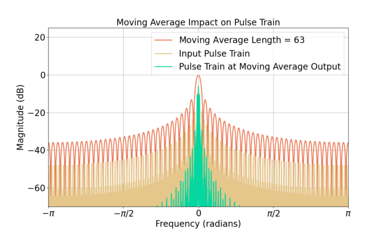
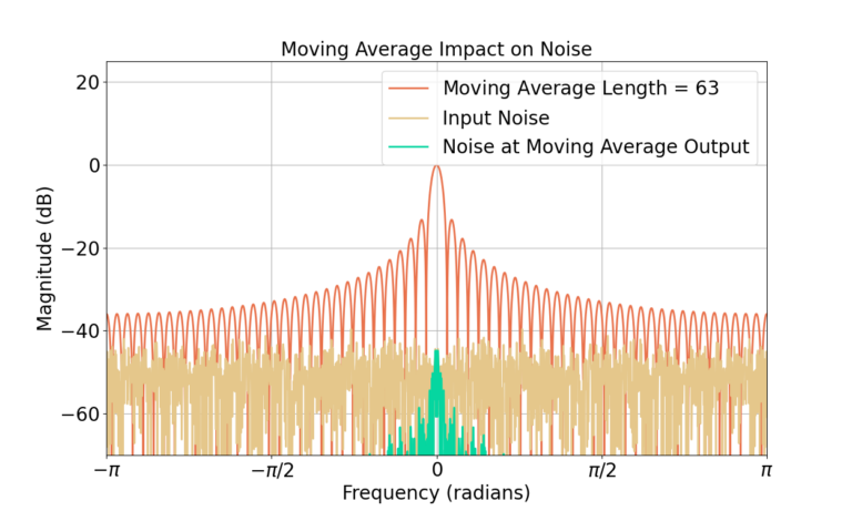
The distortion of the underlying pulse train is also due to the much narrower bandwidth of the MA filter. Figure 15 shows the length-63 MA filter has a much narrower bandwidth than the length-3 MA which results in more attenuation of the high frequency components of the pulse train signal. The noise at the output of the MA filter is also significantly reduced, shown in Figure 16. Also note the length-63 MA filter applies about 38 dB worth of attenuation at high frequencies as compared to 9 dB for the length-3 filter.
Conclusion
The analysis of the FIR filter was used to highlight major concepts within DSP:
- Noise negatively impacts signals.
- Filtering can be used to minimize noise in a receive signal to enhance the signal.
- Trade-offs must be made to balance noise minimization and signal distortion when applying a filter.
- Longer filters provide tend to provide more attenuation than shorter filters.
- Time domain effects can also be viewed through the frequency domain.
More posts on FIR filtering:
![Figure 1: The two sequences for the autocorrelation of x0[n] and x0[n].](https://www.wavewalkerdsp.com/wp-content/uploads/wordpress-popular-posts/5515-featured-125x100.png)

