Table of Contents
Introduction
Today’s DSP Wisdom: odd-lengths are preferable to even-lengths in an FIR filter.
Powers of 2 are ubiquitous in DSP: binary number representations are in base-2, 3 dB is ![]() , and modulations are powers of 2 (BPSK, QPSK, 8-PSK, 16-QAM). The radix-2 FFT is decomposed into 2-input, 2-output butterflies. Upsampling or decimation by 2 can be done efficiently with a half band filter.
, and modulations are powers of 2 (BPSK, QPSK, 8-PSK, 16-QAM). The radix-2 FFT is decomposed into 2-input, 2-output butterflies. Upsampling or decimation by 2 can be done efficiently with a half band filter.
I’ve been allured many times by the siren song of choosing DSP parameters solely because they are powers of 2. A natural fallout is I have typically chosen even parameters for things such as filter lengths because they divide cleanly by a power of 2. The downside is that selecting parameters based on ease of coding results can result in unintended consequences in the DSP.
In this example choosing an even length filter incorporates a fractional time delay at the output of the filter which can negatively effect systems which require precise sampling such as sampling symbols from a demodulator or synchronizing a correlation peak to reference signal.
More blogs on FIR Filters:
Odd Length FIR Filter
A motivating example on the usefulness of odd-length FIR filters is taking a 3-point moving average over a sequence of integers from 0 to 16. The 3-point moving average filter is defined by
(1) ![]()
and the integer sequence
(2) ![]()
Figure 1 is the result of the convolution
(3) ![]()
![Figure 1: The convolution of the moving average filter h3[n] with the sequence of integers x[n].](https://www.wavewalkerdsp.com/wp-content/uploads/2021/11/oddLengthFilters_movingAverageLength3Convolve-2-768x576.png)
Figure 1 shows a delay of 1 sample in the convolution output. The convolution takes a certain number of samples before it starts producing valid outputs due to the time it takes to ramp up and store enough samples in the tapped delay line. The output delay for an even-symmetric FIR filter can be calculated by [lyons2011, p.212]
(4) ![]()
where ![]() is the filter length. For a 3-point moving average filter
is the filter length. For a 3-point moving average filter ![]() the output delay is
the output delay is
(5) ![]()
which is the same delay as in Figure 1.
Ramp Up Delay
The tapped delay line ![]() is initialized with all zeros,
is initialized with all zeros,
(6) ![]()
The multiplication of ![]() with the filter weights initially results in zero,
with the filter weights initially results in zero,
(7) 
The first input sample x[0] is added to the delay line
(8) ![]()
and the filter output is
(9) ![Rendered by QuickLaTeX.com \begin{equation*}y_{3}[0] =\begin{bmatrix}1/3 \\1/3 \\1/3\end{bmatrix}\begin{bmatrix}1, 0, 0\end{bmatrix} = 1/3.\end{equation*}](https://www.wavewalkerdsp.com/wp-content/ql-cache/quicklatex.com-c6a1fad3c0ba39e941fa6355137bbab6_l3.png)
The second input sample x[1] is added to the delay line
(10) ![]()
and the filter output is
(11) ![Rendered by QuickLaTeX.com \begin{equation*}y_{3}[1] = \begin{bmatrix}1/3 \\1/3 \\1/3\end{bmatrix}\begin{bmatrix}2, 1, 0\end{bmatrix} = 1.\end{equation*}](https://www.wavewalkerdsp.com/wp-content/ql-cache/quicklatex.com-f55f95849734c1054c4f1eb604ca912f_l3.png)
The third input sample x[2] is added to the delay line
(12) ![]()
and the filter output is
(13) ![Rendered by QuickLaTeX.com \begin{equation*}y_{3}[2] = \begin{bmatrix}1/3 \\1/3 \\1/3\end{bmatrix}\begin{bmatrix}3, 2, 1\end{bmatrix} = 2.\end{equation*}](https://www.wavewalkerdsp.com/wp-content/ql-cache/quicklatex.com-ca909ee02055ee880e9e6f2f2721455b_l3.png)
After a delay of 1 sample the filter produces valid outputs, ![]() for
for ![]() , as shown in (11) and (13).
, as shown in (11) and (13).
Ramp Down Delay
Just as the convolution has a number of samples associated with ramp up it will have a similar ramp down. The delay (4) at the start of the input sequence came from samples needing to ramp up in the tapped delay line. Similarly a ramp down occurs as input samples are leaving the tapped delay line and being replaced with zeros.
It takes ![]() samples for the tapped delay line to be flushed and from (4)
samples for the tapped delay line to be flushed and from (4) ![]() samples can be removed from the head of convolution leaving
samples can be removed from the head of convolution leaving
(14) ![]()
samples to be removed from the tail end of the convolution.
Correcting for FIR Filter Delay
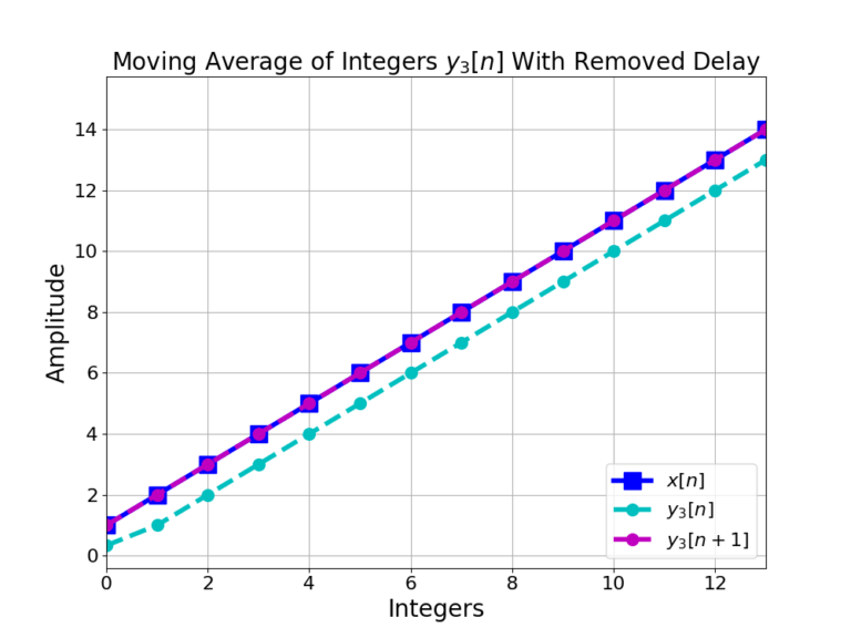
Even Length FIR Filter
A 4-point moving average filter ![]() is convolved with the integer sequence x[n],
is convolved with the integer sequence x[n],
(17) ![]()
which is displayed in Figure 3.
![Figure 3: The convolution of a 4-point moving average FIR filter h4[n] with an integer sequence x[n].](https://www.wavewalkerdsp.com/wp-content/uploads/2021/11/oddLengthFilters_movingAverageLength4Convolve-1-768x576.png)
A delay is seen in the filter output ![]() in Figure 3 similar to the 3-point moving average in Figure 2. However from (4) the delay is
in Figure 3 similar to the 3-point moving average in Figure 2. However from (4) the delay is
(18) ![]()
which is not an integer number of samples. Figure 4 shows the filter output ![]() after removing delays by 1 and 2 samples,
after removing delays by 1 and 2 samples, ![]() and
and ![]() .
.
![Figure 4: The non-integer delay from h4[n] cannot be corrected for by removing a 1 or 2 sample delay as in y4[n+1] or y4[n+2].](https://www.wavewalkerdsp.com/wp-content/uploads/2021/11/oddLengthFilters_movingAverageLength4ConvolveNoDelay-1-768x576.png)
Where the delay-corrected 3-point moving average filter in Figure 2 overlaps perfectly with the input sequence the 4-point moving average filter in Figure 4 has introduced a non-integer sample delay as in (18) that can’t be corrected by removing 1 or 2 samples. Figure 4 shows that ![]() and
and ![]() straddle the input x[n] due to the non-integer sample delay.
straddle the input x[n] due to the non-integer sample delay.
The non-integer sample delay may become a problem in some applications.
Square Root Raised Cosine Filter
A filter with an integer sample delay is particularly important when the output needs to be precisely sampled. An example is a radio receiver sampling symbols at the output of a matched filter. Figure 5 gives the impulse responses for an even and odd length square root raised cosine filter.
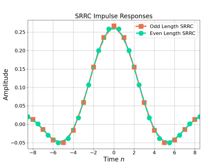
The SRRC parameters between the even and odd length SRRC in Figure 5 are identical except that for the time-indexing: the even length filter is designed with non-integer time values. The even length filter does not have the same peak at ![]() as the odd length filter at n=0. The result is that the receiver with an even length SRRC filter in it will always have a non-optimal sampling time because it cannot sample the peak at n=0.
as the odd length filter at n=0. The result is that the receiver with an even length SRRC filter in it will always have a non-optimal sampling time because it cannot sample the peak at n=0.
You may have noticed that MATLAB’s rcosdesign() function will always give you an odd length. This is why!
Polyphase Filterbanks
In the past I had designed my polyphase filter banks to always have an even number of filter weights because I was overly concerned with computational efficiency. My blindspot was that while I was gaining efficiency I was throwing away fractions of a dB in signal processing gain. This is called “missing the forest for the trees”.
Knowing what I know now I am much more comfortable investing in my signal processing gain by having a handful of zero-weights in my polyphase filterbank coefficients.
Conclusion
Is being off by a 1/2 sample delay a huge deal? No. But consider that the difference between making good systems and GREAT systems is a thousand minuscule tweaks like using odd length filters appropriately.
Here’s an example: one of the most attractive points for getting your algorithm sold, adopted and used is being able to operate at a lower SNR than your competition. Getting down to lower SNR values means saving fractions of a dB everywhere you can and this is one of those tricks that helps get you there. I’ll be sharing more of these tips I’ve learned the hard way in future blog posts.
Resist the urge to make all things, including filter lengths, divisible by 2.
Have you seen the posts on low pass filter design and the half band filter? Ever wondered why their filter lengths are odd? Now you know!
More blogs on FIR Filters:
![Figure 1: The weights of the partitioned half band filter hA[n] and hB[n].](https://www.wavewalkerdsp.com/wp-content/uploads/wordpress-popular-posts/2226-featured-125x100.png)
