![Figure 1: The weights of the partitioned half band filter hA[n] and hB[n].](https://www.wavewalkerdsp.com/wp-content/uploads/wordpress-popular-posts/2226-featured-125x100.png)
![Figure 1: The two sequences for the autocorrelation of x0[n] and x0[n].](https://www.wavewalkerdsp.com/wp-content/uploads/wordpress-popular-posts/5515-featured-125x100.png)
The boxcar filter or boxcar window is an FIR filter whose weights are all 1:
(1) ![\begin{equation*}h_{box}[n] = \begin{cases}1, & 0 \le n \le N-1 \\0, & \text{otherwise}.\end{cases}\end{equation*}](https://www.wavewalkerdsp.com/wp-content/ql-cache/quicklatex.com-7ec10987ed993384eec642f41e636a9f_l3.png "Rendered by QuickLaTeX.com")
The filter weights in (1) are normalized in the time domain to create a moving average (MA) filter
(2) ![\begin{equation*}h_{ma}[n] = \begin{cases}1/N, & 0 \le n \le N-1 \\0, & \text{otherwise}.\end{cases}\end{equation*}](https://www.wavewalkerdsp.com/wp-content/ql-cache/quicklatex.com-1c234a8adf98d1b63905abfc1f2b17bb_l3.png "Rendered by QuickLaTeX.com")
The magnitude-squared of the frequency response for the boxcar window was derived in a previous blog,
(3) 
The moving average is normalized by a factor of 1/N therefore the magnitude-squared of the moving average is normalized by a factor of  ,
,
(4) 
There are multiple bandwidth definitions (see Bandwidth Measures). The focus of this blog is the half-power or 3 dB measure. The 3 dB bandwidth in decibels is
(5) 
The moving average filter is a low-pass filter whose magnitude is the maximum value at  . Therefore to measure the half-energy point the maximum value has to be calculated, which is (4) at ,
(6) 
The 3 dB bandwidth is the frequency  at which the magnitude-squared is 1/2 the maximum value,
(7) 
After substituting (4) equation (7) can now be written as
(8) 
which is simplified to
(9) 
Finding a closed-form solution for (9) is not trivial (see Wolfram’s solution when N=5), but the bandwidth can be approximated as approximately
(10) 
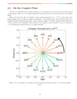
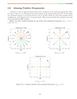
Figures 1-3 show the cutoff frequency approximation (10) for N=5, 10 and 16.
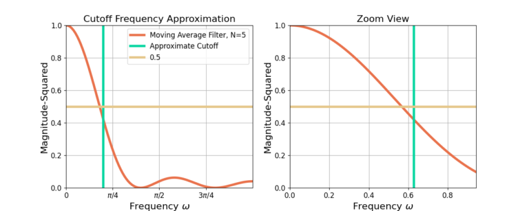
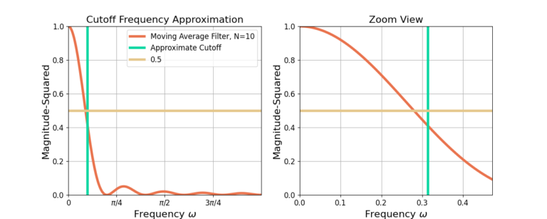
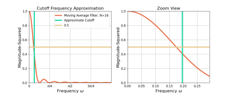
The moving average filter is a normalized boxcar window or boxcar filter. The 3 dB point is where the magnitude-squared is 0.5. The 3 dB bandwidth of a moving average filter length N can be approximated by  .
.
Check out these other blogs!
7 Responses
This estimation approach can be used to determine the cutoff for a MA (lowpass) filter. What if I wanted to construct a MA bandpass filter from two lowpass filters? For example, if the filter length N based on the peak in the spectrum is 120 days, the low passband cutoff would be 38 days (3.14159/120=.02617, 1/.02617=38). Is there a way I cann use this estimation approach to determine the cutoff for the high passband of the MA bandpass filter?
> What if I wanted to construct a MA bandpass filter from two lowpass filters?
Are you required to use a moving average filter? It sounds like you are trying to build up a more sophisticated filter using the moving average as the foundation. I would be hesitant to do this, and I would design a band-pass filter using remez instead (see below).
The MA filter is a specific filter implementation where all of the taps are the same such that it computes the arithmetic mean of the input signal. It’s useful in some contexts but it doesn’t give you much control over the frequency response other than selecting the length N.
From what I can read into your question, it sounds like you need a band-pass filter in which you can specify the lower and upper cutoff frequency independently. If that’s the case I would design a band-pass filter with remez and skip the moving average filter. I have a blog here in which I describe how to do all of this using SciPy’s Remez function: https://www.wavewalkerdsp.com/2021/09/24/designing-fir-band-pass-filters-with-remez/
I hope this helps!
Great. I’ll take a look. Thanks.
If I wanted to do the same estimation technique for a moving average filter with a 0.50 amplitude ratio (-6 db or 0.25 power instead of your example of -3 db or 0.50 power) ) could I just replace 1/2 power in equation 9 with 1/4 power? I know this equation is not solvable but I should be able to get in the ballpark by trial and error.
Are you sure you want a moving average filter in this case? The idea in this post to do analyze a property of the moving average filter, rather than design one. If you want a low-pass filter (which the moving average filter is) with a -6 dB cutoff I would start with this: https://www.wavewalkerdsp.com/2021/09/22/fir-low-pass-filter-design-with-remez/. You’ll note from Figure 2 that the cutoff frequency is designed to be at -6 dB, and then you can design your start/stop/cutoff frequencies as well.
I am fitting a centered moving average filter (I need time domain smoothing, sharp cutoff, and minimal lag) to the Ormsby low pass filter with a -6 db cutoff and many weights (a lot of lag). I used your Wolfram’s link above, changed the equation from 0.50 to 0.25 power, input my Ormsby filter cutoff in angular frequency as x, and used the reduced trigonometric form to solve for N (starting with equation 10 above as my first guess). I was able to narrow down the answer in a couple of tries. As a check, I did a least squares fit of multiple moving averages to the Ormsby filter output and the one I calculated had the lowest SSE. For -3 db, w/(2*pi)=.442946/N. For -6 db, the same is 0.475609/N. BTW, you can get surprisingly close to a very accurate filter like Ormsby with a simple moving average!
Great! Interesting concept of approximating the Ormsby filter, thank you for posting.