Table of Contents
Introduction
The single pole IIR filter is incredibly efficient and can be a great stand-in for a moving average filter! In this blog I describe how to derive the 3 dB bandwidth of the IIR filter to be equivalent to a moving average filter by designing the ![]() weight. The design process builds on the IIR analysis from this DSP Stack Exchange question and my previous blog post.
weight. The design process builds on the IIR analysis from this DSP Stack Exchange question and my previous blog post.
More blog posts on DSP:
Single Pole IIR
The impulse response of the single pole IIR filter is
(1) ![]()
which can also be written as
(2) ![]()
where
(3) ![]()
The magnitude of the frequency response of a single pole IIR filter is given by
(4) ![]()
where the magnitude-squared is
(5) ![]()
Setting up the Design Problem
A previous blog post demonstrated how the 3 dB bandwidth of a moving average filter of length N can be approximated by
(6) ![]()
The goal is to find the value ![]() from (1) such that the 3 dB cutoff frequency of (5) is
from (1) such that the 3 dB cutoff frequency of (5) is ![]() .
.
IIR Filter Design Equation
The 3 dB cutoff corresponds to a magnitude-squared of 1/2. The design equation is therefore
(7) ![]()
Multiplying the complex exponential terms,
(8) ![]()
which is simplified as
(9) ![]()
The complex exponentials can be written in terms of cosine,
(10) ![]()
(11) ![]()
Multiplying the terms of (11) results in
(12) 
Substituting ![]() ,
,
(13) 
Solving with the Quadratic Equation
Picking the Alpha Value
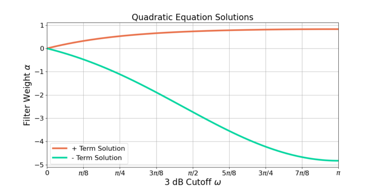
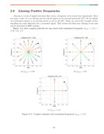
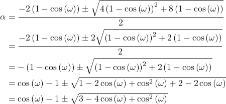
The design equation in (19) has two solutions due to the ![]() term. Figure 1 shows the two solutions for
term. Figure 1 shows the two solutions for ![]() .
.
Approximating the Moving Average Filter
Comparison to Moving Average Filter
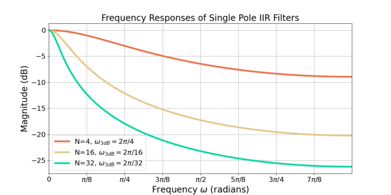
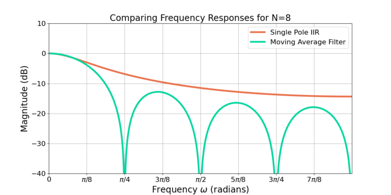
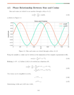
Figure 2 shows that increasing the filter cutoff frequency also reduces the sidelobe attenuation. Although the single pole IIR filter uses less computation than a moving average filter, it also has lower attenuation of out of band frequency content. Figure 3 shows that the single pole IIR filter approaches the response of the moving average filter for N=8 but with about 4 dB worse attenuation.
Conclusion
The single pole IIR filter is a great substitute to the moving average filter! The substitution trades slightly worse sidelobe attenuation for a decrease in computation needed to implement the filter. This blog post described how to design the single pole IIR filter weight to approximate the frequency response of a moving average filter.
More blog posts on DSP:
![Figure 1: The weights of the partitioned half band filter hA[n] and hB[n].](https://www.wavewalkerdsp.com/wp-content/uploads/wordpress-popular-posts/2226-featured-125x100.png)


2 Responses
There is an excellent paper “Low-pass filters for signal averaging” by
Edward Voigtman and James D. Winefordner. I provide the citation link below.
In it, they explain how the ideal filter for this application is the integrator, one embodiment of which is the moving average together with a proper antialiasing filter. The single-pole IIR filter unfortunately does a terrible job at the proper metric for this application which is the product of settling time x noise bandwidth. In other words, tracking of sidelobes doesn’t matter when you’re averaging; what matters is how fast it settles to the right value and how much noise it lets through.
If simplicity over performance is the target while still retaining low memory usage, you will do much much better by cascading three to six identical IIR single-lowpass of the type described in this article and adjusting the corner to meet your needs. It’s called a synchronous filter (hard to find in filter literature since it’s not a good filter for anything but averaging time series) and will approximate a Bessel filter for this data-averaging application.
Citation: 57, 957 (1986); doi: 10.1063/1.1138645
View online: http://dx.doi.org/10.1063/1.1138645
View Table of Contents: http://aip.scitation.org/toc/rsi/57/5 Published by the American Institute of Physics
Great insights and interesting paper, thank you!