Table of Contents
Introduction
A comb filter is a multiplier-less filter, meaning it only uses additions when computing the impulse response. The comb filter is one of the two major building blocks in the cascaded integrator comb (CIC) filter.
This blog post will describe both the impulse response and frequency response of the comb filter and demonstrate how to analyze the comb filter in the frequency domain.
Related DSP blogs:
Comb Filter Time Domain
The difference equation for the comb filter is defined by [harris2021,p.395]:
(1) ![]()
where ![]() which is the delay between the two samples being added.
which is the delay between the two samples being added.
Comb Filter Frequency Domain
It is difficult to assertain the impact of the filter only looking at the time domain in (1) but transformation into the frequency domain can make the analysis easier. Apply the Z-transform:
(2) ![]()
and combine like terms:
(3) ![]()
The transfer function H(z) is therefore
(4) ![]()
Substituting ![]() , the frequency response is therefore
, the frequency response is therefore
(5) ![]()
The magnitude-squared of the the frequency response is therefore
(6) 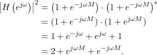
Using Euler’s formula (6) can be written as
(7) 
Comb Filter Passband Analysis
The maximum values, or pass-bands, of the comb filter’s frequency response (7) occur when
(8) ![]()
such that
(9) ![]()
Using an example to illustrate (8), a comb filter with a delay M=2 will have maxima when
(10) ![]()
Substituting ![]() ,
,
(11) ![]()
when
(12) ![]()
therefore the maxima of the passband occur at
(13) ![]()
The values of ![]() in (13) are limited to
in (13) are limited to
(14) ![]()
because it is a discrete-time filter and ![]() and
and ![]() correspond to the negative sampling frequency and positive sampling frequency in radians.
correspond to the negative sampling frequency and positive sampling frequency in radians.
Comb Filter Stopband Analysis
The minimum values, or stop-bands, of the comb filter’s frequency response occur when
(15) ![]()
such that
(16) ![]()
Using an example to illustrate (15), a comb filter with a delay M=2 will have minima when
(17) ![]()
Substituting ![]() ,
,
(18) ![]()
when
(19) ![]()
therefore the minima of the passband occur at
(20) ![]()
Examples of Comb Filter Frequency Responses
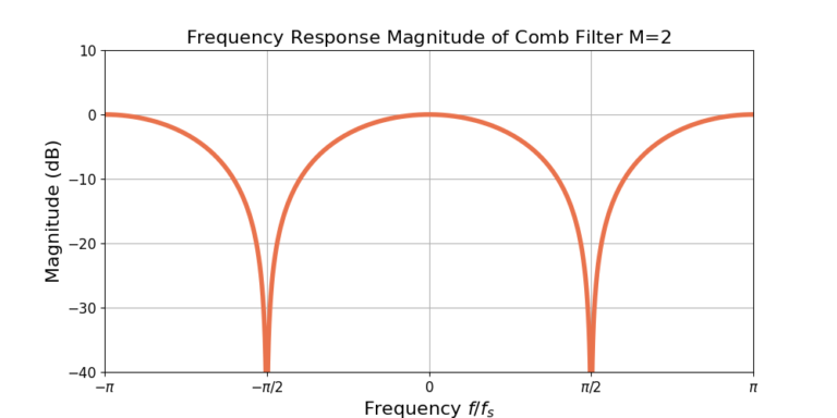
Increasing the delay M results in more passbands and more stopbands. Figure 2 gives the magnitude of the frequency response for M=4.
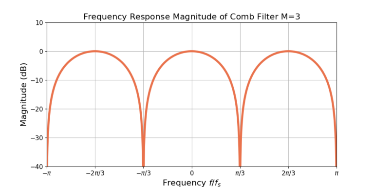
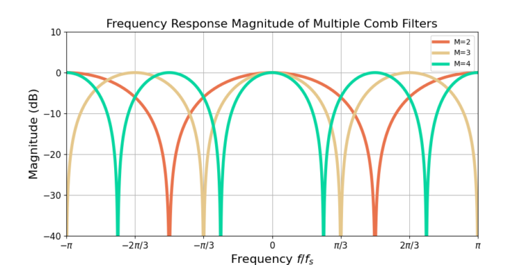
Figure 3 gives the responses for three different comb filters: M=2, 3 and 4. Increasing the delay M results in more maxima and more minima, which appear as more teeth in the comb. Increasing the delay M also narrows the teeth of the comb.
Conclusion
The comb filter is multiplier-less filter, making it efficient to implement. The comb filter is also one half of the cascaded integrator comb (CIC) filter. The blog described both the impulse response and frequency response of the comb filter. Analysis was also performed on the passbands and stopbands of the frequency response.
Related DSP blogs:
- Minimizing Filter Length: Explaining Why
- FIR Low Pass Filter Design With Remez
- Single Pole IIR: Substitute for Moving Average Filter
![Figure 1: The two sequences for the autocorrelation of x0[n] and x0[n].](https://www.wavewalkerdsp.com/wp-content/uploads/wordpress-popular-posts/5515-featured-125x100.png)
5 Responses
Nice article thanks
Is that error that (5) equation does not have M in the exponent?
Yes! Thank you, and I’ve updated the equation.
Hi,
Matlab freqz does not agree with your plots. for example:
num =[1, 0, 0, 0, -1] for M= 4
freqz(num,1) and see plot is high pass filter.
Any thoughts please?
Kadhiem
Change the -1 into a +1
num = [1, 0, 0, 0, 1]