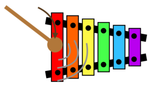
![Figure 4: The PFB half band filter structure after folding the even-symmetric filter weights hA[n] and ignoring the zero weights in hB[n].](https://www.wavewalkerdsp.com/wp-content/uploads/2021/10/polyphaseHalfBandFoldedNoZeroMultiply-300x226.png)
Folding a Polyphase Half Band Filter: Lemon Squeezer Style
Folding a filter is a way to improve efficiency, and folding the weights for a polyphase filterbank improves the efficiency beyond that. The zero weights in the half band filter make for a great application of the folding and polyphase filterbank structures.
You know after you cut a lemon and try to get the juice out by hand you get to the point where you need a lemon squeezer to get every last drop? This blog is going to squeeze out every little bit of efficiency in the polyphase half band filter.

![Figure 1: The weights of the partitioned half band filter hA[n] and hB[n].](https://www.wavewalkerdsp.com/wp-content/uploads/2021/09/halfBandFilterPolyphase_HBFImpulseResponsePolyphasePartition-1-300x180.png)
Polyphase Half Band Filter for Decimation by 2
The last post on half band filters (HBF) referenced the use of a polyphase filter bank structure with a half band filter of length N can be reduced to N/8 multiplies per input sample. This is a huge efficiency gain and why they are used in large sample rate change [harris2021, p.234]. The polyphase filter bank will be used to efficiently implement a decimation by 2 within the HBF with additional savings coming from folding the filter weights. A polyphase filterbank is characterized by multiple branches which represent multiple phases of the signal (the prefix poly- meaning “many”.)
Half Band Filter Design: Exceptional Filtering Efficiency!
Introduction The half band filter (HBF) is an incredibly efficient filtering structure when designed correctly! In this blog I will discuss how to design half

The Wisdom of Conan O’Brien
I’m particularly fond of two pieces of wisdom from Conan O’Brien.
Designing an FIR Band Pass Filter with Remez
Introduction A band pass filter is characterized by having attenuation at both high frequency and low frequency with a pass-band in between. Band-pass filters can
Designing an FIR High Pass Filter with Remez
Introduction While low-pass filtering (LPF) is ubiquitous high pass filters (HPF) can be needed depending on the RF environment or for specific algorithms. The previous
FIR Low Pass Filter Design with Remez
Introduction The focus of this blog is to describe the low pass filter design process with the remez() function, which is one of many ways

Engineering Mindset: Be a Stone Carver, not a Brick Mason
Maintaining the proper mindset is crucial to proper mental health and the longevity of your career. Many come to believe that engineering is linear and procedural, like a brick mason building a brick wall. The brick mason operates by adding more and more material; bigger is better, more expensive and more profitable.
A more effective mindset is that of the stone carver. Quality and craftsmanship are key for the stone carver. A stone carver designs one chisel stroke at a time. The stone carver removes what does not belong until the final design is revealed. For the stone carver, less is more: removing more material allows for more detail, more polish and represents an overall a higher quality piece of art.
Why are Sinusoids used in DSP and RF?
The goal of this post is to shed some light on why sinusoids are useful in DSP and RF communication.
Sinusoids are used by humans to describe the cyclical nature of the universe. They are a useful mathematical abstraction. Each year is 365 days and then a new year begins. Spring is followed by summer, fall, winter and then spring begins again. Low tide, high tide and then low tide again. A spinning ceiling fan. The rotation of the tires on your automobile. Reeling your fishing rod.